Front brake disk and pad replacement Jeep Wrangler (JL) 2018-

1. Raise and support your vehicle
Video
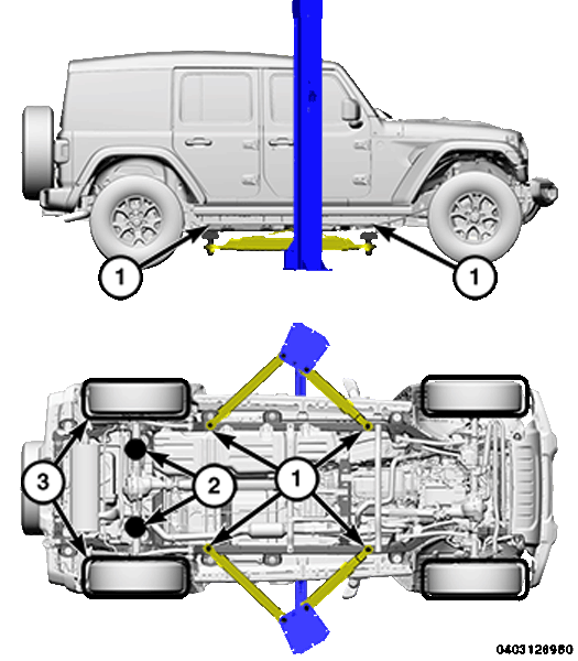
Lifting points
- 1. FRAME CONTACT LIFT (SINGLE POST)
- 1. CHASSIS LIFT (DUAL LIFT)
- 1. OUTBOARD LIFT (DUAL LIFT)
- 2. ALTERNATE LIFTING LOCATIONS
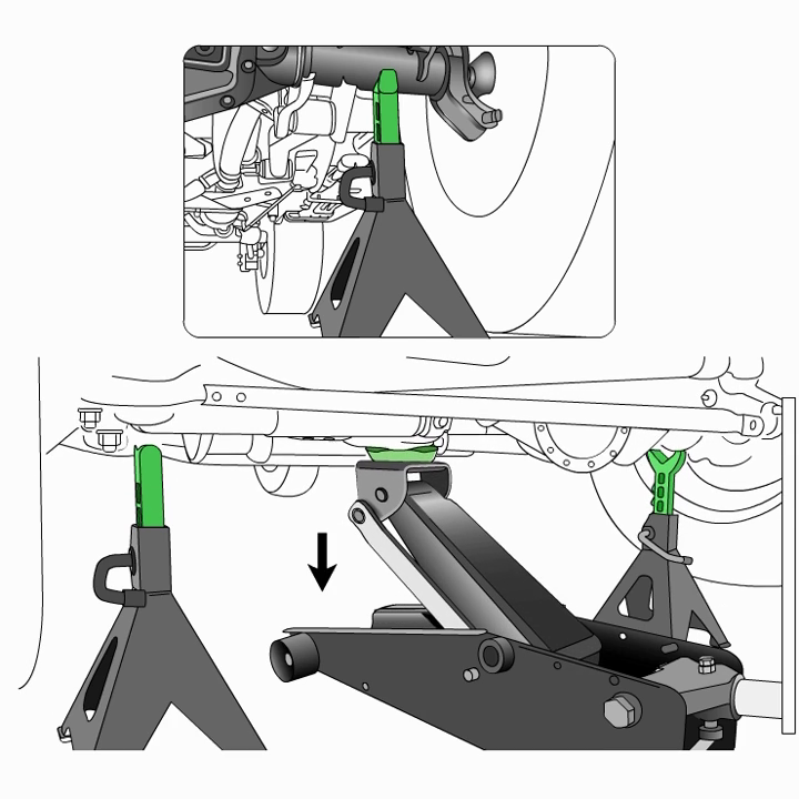
- 2. FLOOR JACK
- 3. DRIVE ON HOIST
Refer to the Owner's Manual for emergency vehicle lifting procedures. When properly positioned, a floor jack can be used to lift a Jeep vehicle. Support the vehicle in the raised position with jack stands at the front and rear ends of the frame rails. Do not attempt to lift a Jeep vehicle with a floor jack positioned under:
- A body side sill.
- A steering linkage component.
- A drive shaft.
- The engine or transmission oil pan.
- The fuel tank.
- A front suspension arm.
- Transfer case.
Use the correct sub-frame rail or frame rail lifting locations only.
When a frame-contact type hoist is used, verify that the lifting pads are positioned properly.
The hoisting and jack lifting points provided are for a complete vehicle. When a chassis or drivetrain component is removed from a vehicle, the center of gravity is altered making some hoisting conditions unstable. Properly support or secure vehicle to hoisting device when these conditions exist.
2. Remove the front wheel and tire assembly
Video
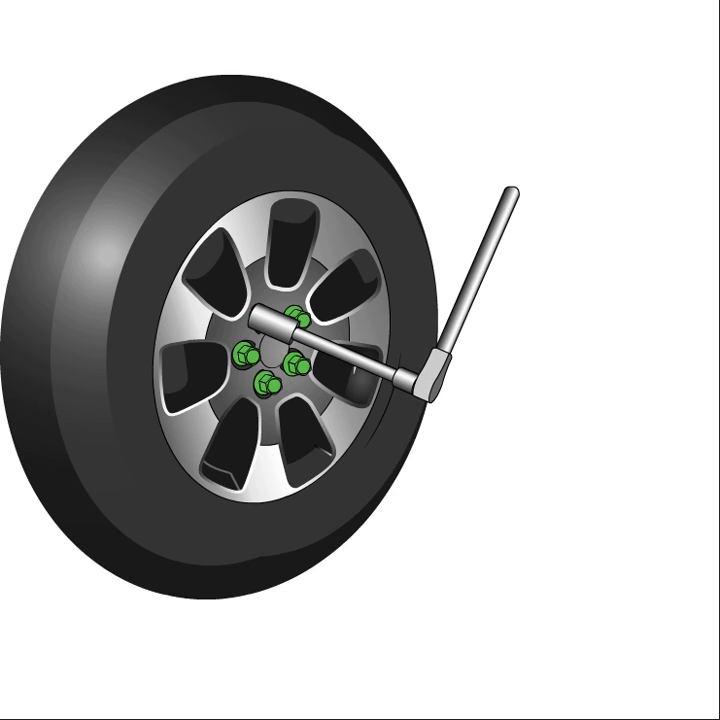
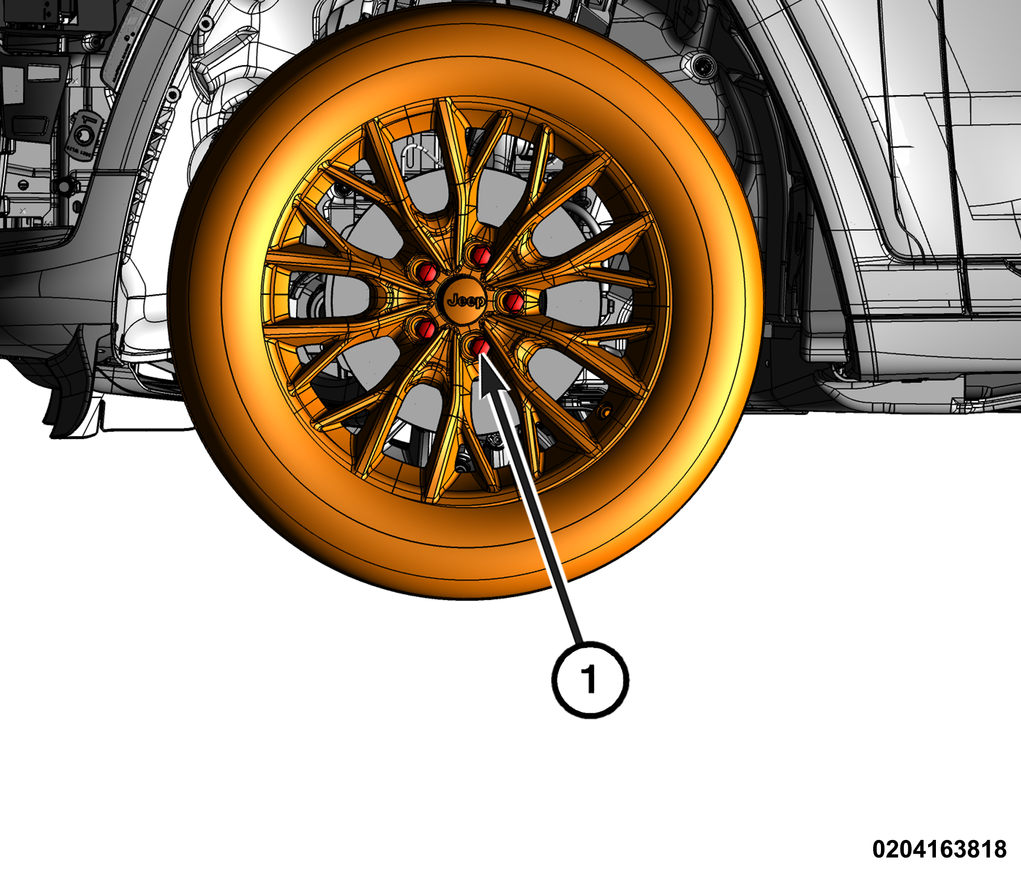
- Lug nuts
- Remove the lug nuts
- Remove the tire and wheel assembly
3. Separate the brake caliper from the caliper adapter
Video

- Remove the front caliper adapter and front caliper as an assembly
- Separate the brake caliper from the caliper adapter
- Using a brake pedal holding tool, depress brake pedal past its first inch of travel and hold it in this position. Holding pedal in this position will isolate master cylinder from hydraulic brake system and will not allow brake fluid to drain out of brake fluid reservoir while brake lines are open.
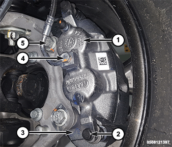
- Brake Caliper
- Caliper Bolts
- Caliper Adapter
- Brake Hose Banjo Bolt
- Caliper Adapter Bolt
- Remove the brake hose banjo bolt and Discard two copper gaskets
- Remove the two caliper bolts
- For light duty sport models only. Prior to removing the caliper, use a suitable clamp tool to press the outboard brake pad away from the brake caliper to break the brake pad and the brake caliper. adhesive bond between the
- Remove the brake caliper
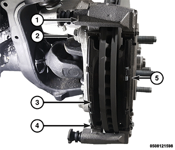
4. Remove the brake caliper
Video

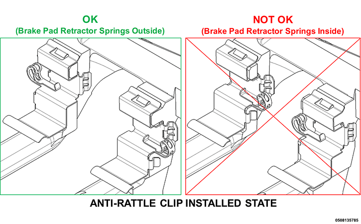
For light duty sport models only, brake pads and anti-rattle clips must be removed and discarded.
In some cases, it may be necessary to retract the caliper pistons into their bores a small amount in order to provide sufficient clearance between the pads and the rotor to easily remove the caliper from the adapter. Never push on pistons directly as it may get damaged.
- Brake Caliper
- Caliper Bolts
- Caliper Adapter
- Brake Hose Banjo Bolt
- Caliper Adapter Bolt
- Remove the two caliper bolts.
- Separate the caliper from the adapter then position the caliper aside and ensure that it is securely supported. Do not allow brake hose to support caliper weight.
- Caliper Adapter
- Caliper Adapter Bolts
- Inboard Brake Pad
- Anti-Rattle Clips
- Outboard Brake Pad
5. Remove the brake rotor
Video

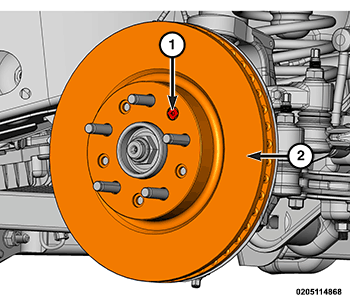
- Front Rotor Screw
- Brake Rotor
- Remove the front rotor screw
- Remove brake rotor
6. Installation
Video

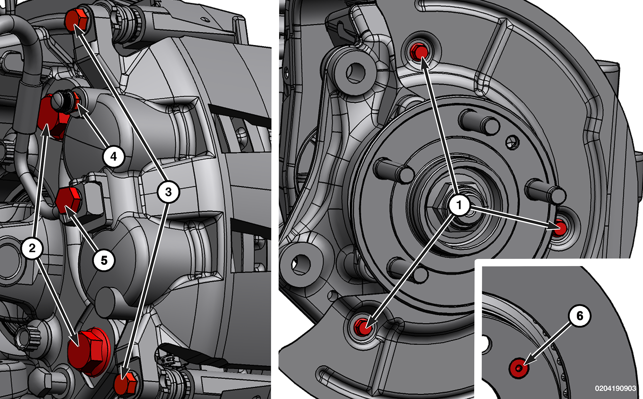
During installation, torque the fasteners to the specifications in the torque table(s) below.
| DESCRIPTION | SPECIFICATION |
| Brake Rotor Splash Shield Bolts | 11 N⋅m (8 Ft. Lbs.) |
| Front Caliper Adapter Bolts | 200 N⋅m (148 Ft. Lbs.) |
| Front Caliper Bolts | 37 N⋅m (27 Ft. Lbs.) |
| Front Caliper Bleed Screw | 10 N⋅m (7 Ft. Lbs.) |
| Front Caliper Brake Hose Banjo Bolt | 35 N⋅m (26 Ft. Lbs.) |
| Front Rotor Screw | 20 N⋅m (15 Ft. Lbs.) |
Follow the removal procedure in reverse for general reassembly of the components on the vehicle. The steps listed below are calling out specific procedures that should be followed during installation.
When NEW brake pads have been installed, keep in mind that braking effectiveness might be somewhat reduced during the first brake applications following installation. Verify that the brake hose is not twisted or kinked before tightening banjo bolt. Install two NEW copper washers.
- Using a suitable tool press both caliper pistons as necessary into the caliper bores.
- Be certain that the anti-rattle clip mounting surfaces of the caliper adapter are free from rust and debris.
- The four NEW anti-rattle clips must be installed as shown.
- Install the four NEW anti-rattle clips.
- Pump brake pedal until caliper pistons and brake pads are seated and a firm brake pedal is obtained.
- Verify proper brake fluid level.
- Tighten the lug nuts in a star pattern.
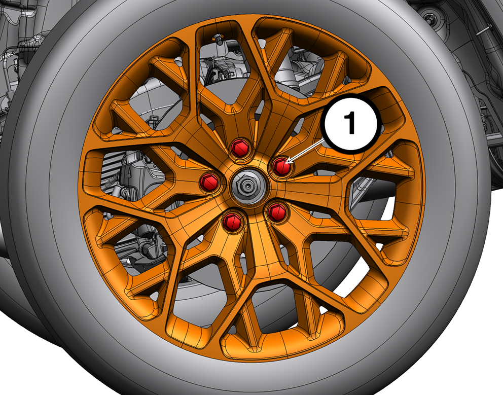
| DESCRIPTION | SPECIFICATION | LUG NUT SIZE | LUG NUT SOCKET SIZE | |
| 1 | Lug Nut | 176 N·m (130 Ft-Lbs) | M14 x 1.50 | 22 mm |
Use only authorized dealer recommended lug nuts and clean or remove any dirt or oil before tightening.
Road test vehicle making several stops to wear off any foreign material on brakes and to seat brake shoes.
7. Bleeding
- Fill the master cylinder reservoir with brake fluid prior to connecting pressure bleeder.
- Fill the bleeder tank with recommended fluid and purge air from the tank lines before bleeding.
Caution: Follow the manufacturers instructions carefully when using pressure equipment. Do not exceed the tank manufacturers pressure recommendations. Generally, a tank pressure of 51-67 kPa (15-20 psi) is sufficient for bleeding.
- Connect the pressure bleeder to the master cylinder using adapter provided with the equipment.
Note: When pressure bleeding, a helper is needed inside the vehicle.
- Bleed only one brake component at a time in the following sequence, as follows:
- Right rear
- Left rear
- Right front
- Left front
- Attach one end of a clear bleed hose to the bleed screw and insert the opposite end in a suitable container (see illustration).
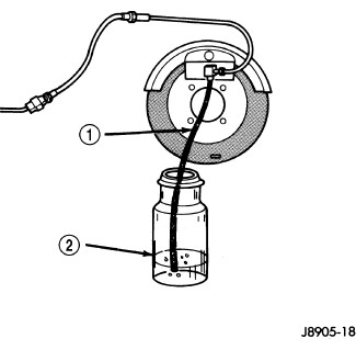
- Open the bleeder and have the helper pump the brake pedal multiple times, until the fluid stream is clear and free of air bubbles, then with the brake pedal pushed, tighten the bleeder screw.
- Repeat this process on each wheel until all are complete.
- After the Pressure Bleeding procedure, connect the scan tool to the Data Link Connector.
- Select ANTILOCK BRAKES, followed by MISCELLANEOUS, then ABS BLEED BRAKES and follow the instructions displayed for the procedure.
- Remove the bleeder hose, and the pressure bleeder from the master cylinder.
- If the ABS module was replaced, perform the ABS VERIFICATION TEST.
- Verify proper brake operation before moving the vehicle.